

 русский




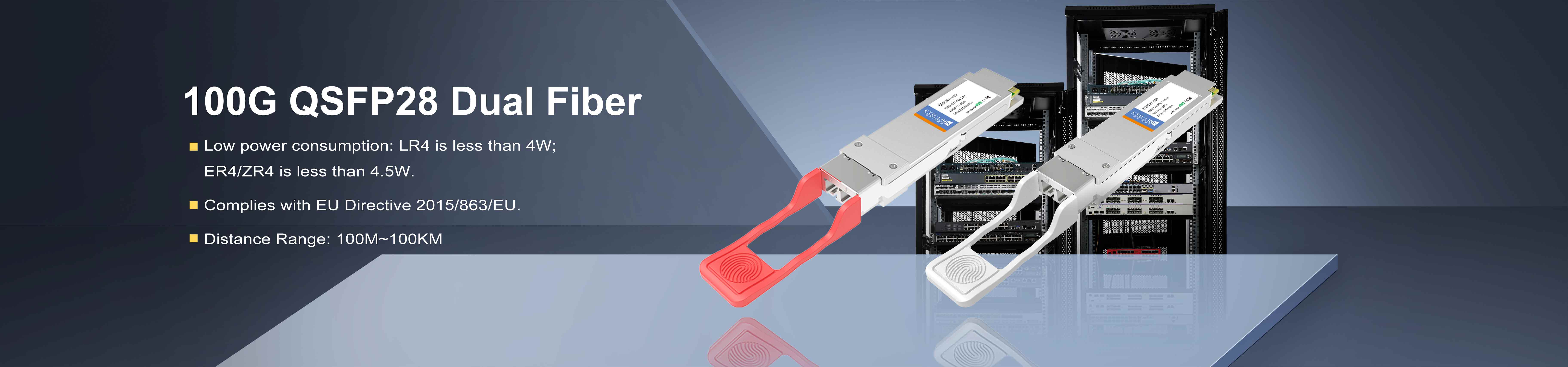
What Are The Key Test Equipment For 800G Optical Modules?
AI computing infrastructure is expanding at full speed. 800G OSFP and QSFP-DD Optical Modules have fully entered the market adoption cycle. The industry is generally showing a differentiated pattern where leading manufacturers are operating at full capacity and order schedules are lengthening, while small and medium-sized manufacturers are accelerating production expansion to grab market share. The Accuracy of Equipment Selection, the Strength of Technical Manufacturers, and the Stability of Supply Partners have become the three core keys for companies to break through.
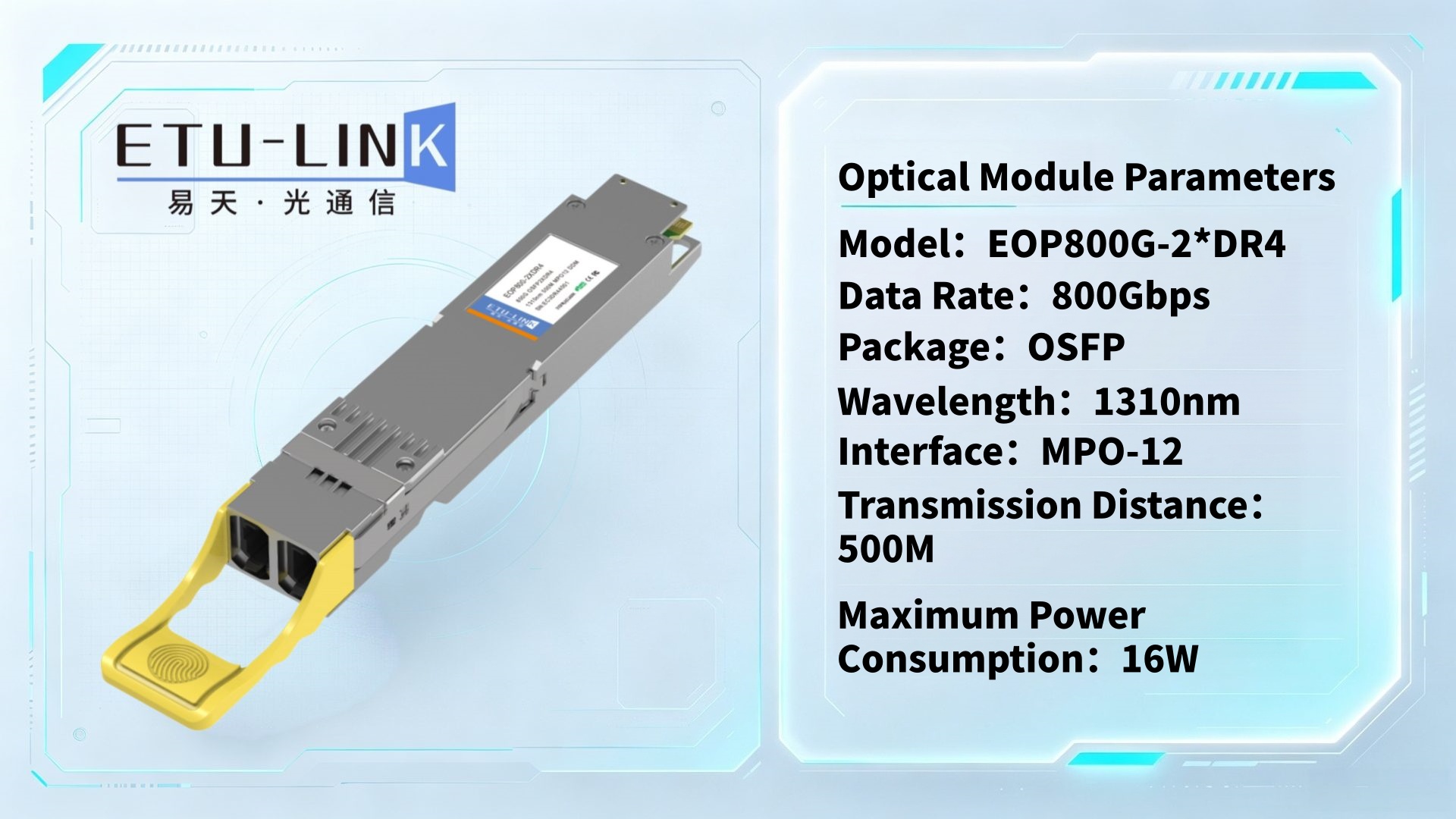
ETU-LINK has made forward-looking plans for the research and development of a full range of 800G optical modules, equipped with a complete set of standardized 800G testing equipment, and built a high-standard dust-free production workshop. It independently completes the entire process of incoming material inspection, performance calibration, three-temperature testing, aging screening and final inspection of finished products.
Its product design strictly follows international industry standards, and its solutions have the potential for long-term high reliability. It has outstanding advantages in quality control, cost-effectiveness, and delivery response capabilities, and will become a reliable alternative supplier of 800G optical modules for customers!
Superior product quality relies on a comprehensive testing system and professional testing equipment. Below, from ETU-Link Technology Co., Ltd. perspective, we'll break down the key testing equipment and core testing items essential for the mass production and R&D of 800G OSFP/QSFP-DD optical modules.
Ⅱ.Vocabulary Analysis
| Noun | Full Name |
| SMSR | Side-Mode Suppression Ratio |
| DFB | Distributed Feedback Laser |
| PAM4 | 4-level Pulse Amplitude Modulation |
| TDECQ | Transmitter and Dispersion Eye Closure Quaternary |
| TJ/RJ shaking | TJ=Total Jitter ; RJ=Random Jitter |
| Tx/Rx | Tx=Transmitter ; Rx=Receiver |
| LD | Laser Diode |
| EVM | Error Vector Magnitude |
| VOA | Variable Optical Attenuator |
| TIA | Transimpedance Amplifier |
Ⅲ.Optical Chip/Device Testing
1.Semiconductor Parameter Analyzer (SPA ):Measures LIV curves of VCSEL/EML/DBF.
2.Optical Spectrum Analyzer (OSA ): Measures center wavelength, spectral width, SMSR side-mode suppression ratio, and wavelength temperature drift (essential for DFB).
3.Bandwidth Tester: (LCA, Lightwave Component Analyzer) Small signal response, bandwidth, S-parameters.
4.Noise Figure/PD Parameter Tester: PD photodetector responsivity, dark current, TIA input noise.
Ⅳ.Transmitter and Receiver Sub-Tests for Full-Duplex PAM4 Testing of 800G Optical Modules
1.Optical Transmitter Testing
The optical signal is driven by a bit error rate tester. The eye diagram, TDECQ, and jitter are measured by an optical waveform oscilloscope. The wavelength and SMSR are measured by a spectrum analyzer, and the optical power is measured by an optical power meter. During the process, a programmable power supply and an I2C debugger are required to power on the module and configure the registers .
(1).Bit Error Rate Tester (BERT): Supports 53.125Gbaud PAM4 (800G commonly uses 8×100G or 4×200G).
(2).Digital Communications Analyzer (DCA): Measures emission eye diagram, extinction ratio, TDECQ, TJ/RJ jitter, and overshoot.
(3).Pulse Pattern Generator (PPG ): generates standard test codes and transmits input electrical signals to the module.
(4).Optical Power Meter: measures average Tx optical power and detects light leakage during shutdown.
(5).Optical Attenuator + Optical Switch: Multi-channel automated testing
(6).Programmable DC Power Supply: supplies power to the module and monitors the LD bias current and overall power consumption.
(7).I2C Read/Write Debugger: Reads DDM Digital Diagnostic Registers (OSFP/QSFP-DD/SFP Universal)
2.Optical Receiver Testing
The closed-loop testing method is adopted: the TX end generates a signal from the bit error rate analyzer or code generator → it is converted into an optical signal by the optical module → it passes through the attenuator and scrambler → it is received by the optical module under test → and the bit error rate is analyzed back to the bit error rate analyzer.
(1).High-speed Bit Error Rate Tester (BERT): Rx sensitivity, saturation overload optical power, BER ≤ 2.4×10⁻⁴
(2).Optical Modulation Analyzer: Performs EVM and TDECQ analysis on PAM4 signals.
(3).Adjustable-Attenuation Light Source: programmable adjustable optical attenuator+continuously adjustable laser LD
1) Programmable VOA: Precise scanning sensitivity (minimum received optical power), step 0.01dB, scan sensitivity / saturation point
Следующий :
Каковы технические особенности 400G QSFP-DD LR4?Категории
Новый блог
Теги
новые продукты
Оптический трансивер 800G OSFP 2×DR4 1310nm 500M MPO12 с DDM Читать далее
100G QSFP28 ZR4 BIDI 80KM LC оптический трансивер Читать далее
Оптический трансивер 1.25G SFP 1550 нм 200 км LC Читать далее
Оптический трансивер 10G SFP+ ZR 1550 нм 120 км LC Читать далее
Оптический приемопередатчик 100G QSFP28 LR с одинарной лямбдой 10 км LC Читать далее
Оптический приемопередатчик 25G SFP28 ZR 1310 нм 80 км LC Читать далее
Оптический приемопередатчик 100G QSFP28 ZR4 80KM LC поколения II Читать далее
Оптический приемопередатчик 100G QSFP28 BIDI 40 км LC Читать далее
По вопросам о наших продуктах или прайс-листе, пожалуйста, оставьте нам, и мы свяжемся с вами в течение 24 часов.


 Factory: Right Side Of 3rd Floor, No. 102 Building, Longguan Expressway, Dalang Street, Longhua District, Shenzhen
Office: Floor 4, Building 4, Nanshan Yungu Phase ll, Taoyuan Community, XiliStreet,Nanshan District, Shenzhen
© Авторские права: 2026 ETU-Link Technology CO ., LTD Все права защищены.

Поддерживается сеть IPv6


