

 русский




Откуда берутся данные об оптическом бюджете?
При проектировании оптических коммуникационных сетей один из наиболее часто задаваемых инженерам вопросов звучит так: «Как далеко это оптическое волокно действительно может передавать сигнал?» На первый взгляд это простой вопрос, но за ним скрывается строгая система расчётной логики. Сегодня разберём, как рассчитывается дальность передачи оптического модуля.

Ⅰ.Два главных препятствия: потери и дисперсия
Дальность передачи оптического модуля в основном ограничивается двумя факторами: потерями и дисперсией.
Потери означают потерю оптической энергии, вызванную поглощением, рассеянием и утечкой в среде при передаче оптического сигнала по оптическому волокну. Чем дальше распространяется оптический сигнал, тем больше затухание энергии.
Дисперсия, с другой стороны, представляет собой другое явление—свет с разными длинами волн распространяется в одной и той же среде с разной скоростью. По мере увеличения расстояния передачи оптический импульс расширяется, что в конечном итоге приводит к невозможности правильной интерпретации сигнала приёмником.
Проще говоря, потери — это «ослабление сигнала», а дисперсия — это «размывание сигнала». Когда оба ограничения существуют одновременно, фактическая максимальная дальность передачи определяется меньшим из двух значений.
Ⅱ.Расчёт в три этапа: классическая формула ограничения по потерям для оптического волокна ограничения по потерям
Основная формула расчёта дальности передачи при ограничениях по потерям очень проста:
Дальность, ограниченная потерями = (мощность передаваемого оптического сигнала − чувствительность приёмника) / коэффициент затухания волокна
Мощность передаваемого оптического сигнала и чувствительность приёмника выражаются в dBm, а коэффициент затухания волокна выражается в dB/km.
Здесь появляется технический термин: бюджет линии —разница между мощностью передаваемого оптического сигнала и чувствительностью приёмника.
В стандарте Международного союза электросвязи (ITU-T) типичная оценка потерь для одномодового оптического кабеля составляет 0,35 dB/km для длины волны 1310 nm и 0,25 dB/km для длины волны 1550 nm.
На примере широко используемого оптического волокна G.652 типичный коэффициент затухания составляет 0,30~0,40 dB/km в окне 1310 nm и всего 0,20~0,22 dB/km в окне 1550 nm.
Возьмём оптический модуль 10G 1500nm ER в качестве примера:
Расчёт линии = мощность передачи (наиболее консервативное значение) - чувствительность приёмника = (-4) - (-16) = 12 dB
Теоретическое расстояние = Бюджет линии ÷ Затухание в волокне (0,25 дБ/км) = 12 ÷ 0,25 = 48 км
Фактически заявленное расстояние = Теоретическое расстояние - Инженерный запас (включая потери на разъёмах, изгибах и другие потери) = 48 км - 8 км = 40 км
Ⅲ.Длина волны определяет назначение: 1310 нм против 1550 нм
Выбор длины волны напрямую влияет на дальность передачи.
Волокно G.652 имеет чрезвычайно низкую дисперсию на длине волны 1310 нм, что делает его подходящим для передачи на короткие расстояния; при этом затухание является минимальным на длине волны 1550 нм, что делает его подходящим для передачи на большие расстояния. Коэффициент затухания на длине волны 1550 нм составляет примерно 2/3 от значения на 1310 нм, поэтому теоретически оно может обеспечивать передачу на большие расстояния.
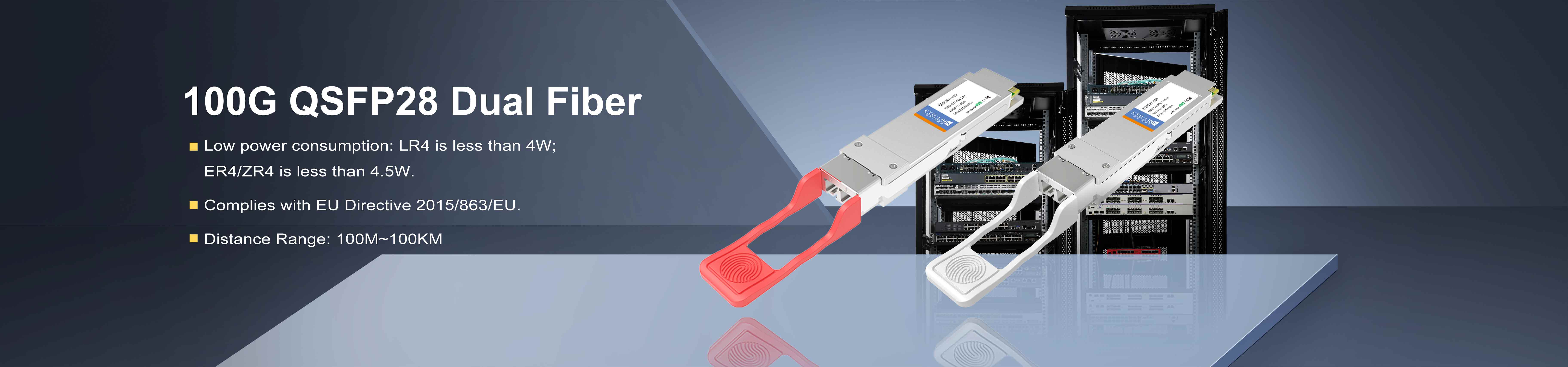
Эта логика расчёта также применяется к различным распространённым спецификациям оптических модулей, таким как серии QSFP/QSFP28, которые следуют тем же принципам ограничения потерь и дисперсии. Более высокие скорости передачи (например, 100G, 400G и выше) обычно требуют более сложных методов когерентной модуляции для преодоления влияния нелинейных эффектов, таких как дисперсия, на передачу данных на большие расстояния.
«Скрытые потери» в реальной инженерной практике
Теоретически рассчитанное расстояние является только справочным значением. В реальной инженерной практике такие факторы, как разъёмы, сварные соединения и потери на изгибах, будут потреблять дополнительную оптическую мощность. Обычно рекомендуется учитывать инженерный запас в размере 2–3 дБ в результатах расчёта, чтобы гарантировать стабильную работу сети даже в таких условиях, как старение оборудования и колебания температуры.
Если вам нужны высококачественные и стабильные оптические модули, вы можете узнать больше о ETU- LINK.
Категории
Новый блог
Теги
новые продукты
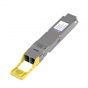
Оптический трансивер 800G OSFP 2×DR4 1310nm 500M MPO12 с DDM Читать далее
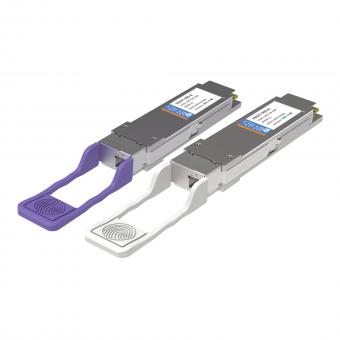
100G QSFP28 ZR4 BIDI 80KM LC оптический трансивер Читать далее
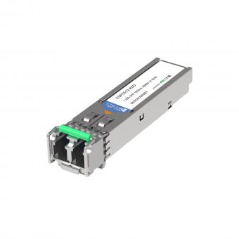
Оптический трансивер 1.25G SFP 1550 нм 200 км LC Читать далее
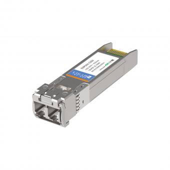
Оптический трансивер 10G SFP+ ZR 1550 нм 120 км LC Читать далее
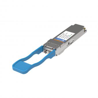
Оптический приемопередатчик 100G QSFP28 LR с одинарной лямбдой 10 км LC Читать далее
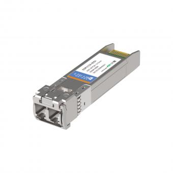
Оптический приемопередатчик 25G SFP28 ZR 1310 нм 80 км LC Читать далее
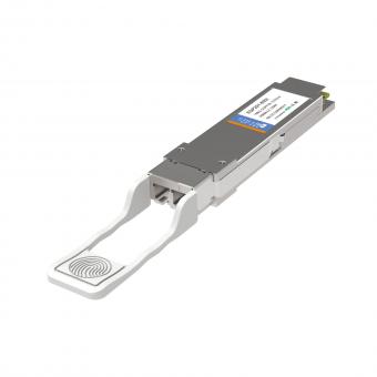
Оптический приемопередатчик 100G QSFP28 ZR4 80KM LC поколения II Читать далее
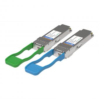
Оптический приемопередатчик 100G QSFP28 BIDI 40 км LC Читать далее
По вопросам о наших продуктах или прайс-листе, пожалуйста, оставьте нам, и мы свяжемся с вами в течение 24 часов.


 Factory: Right Side Of 3rd Floor, No. 102 Building, Longguan Expressway, Dalang Street, Longhua District, Shenzhen
Office: Floor 4, Building 4, Nanshan Yungu Phase ll, Taoyuan Community, XiliStreet,Nanshan District, Shenzhen
© Авторские права: 2026 ETU-Link Technology CO ., LTD Все права защищены.

Поддерживается сеть IPv6


